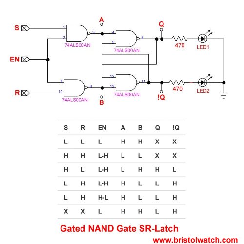
Gated S R Latch Truth Table

In the s r latch we have seen that output changes occur immediately after the input changes occur i e the latch is sensitive to its s r inputs at all times.
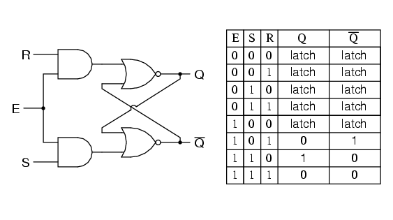
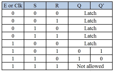
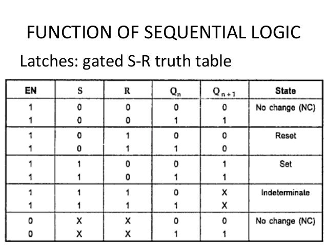
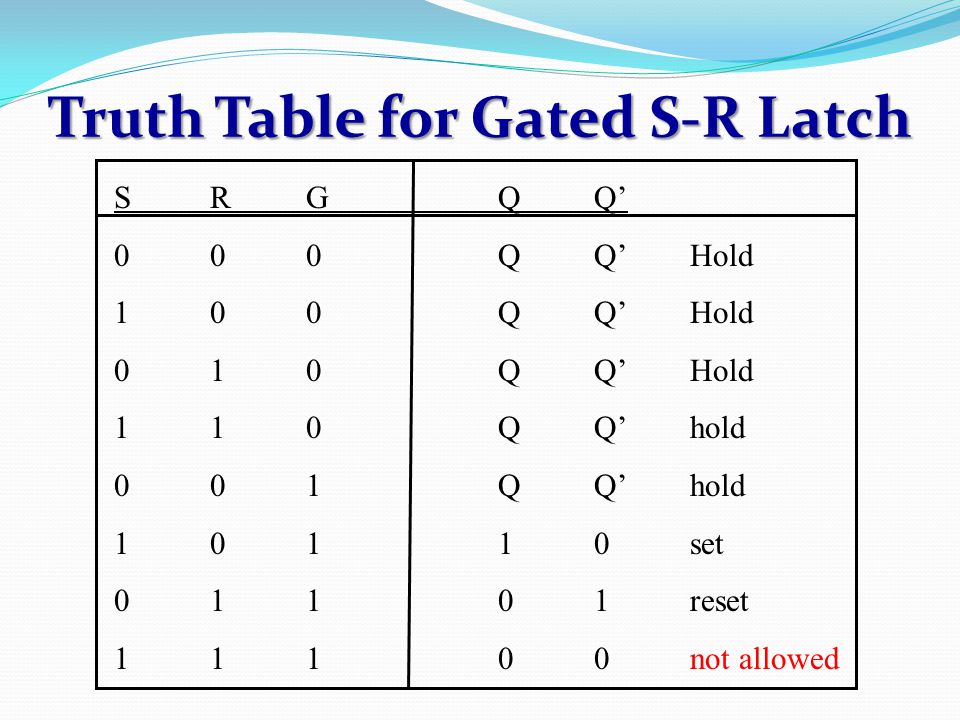
Gated s r latch truth table. Gated d latch d latch is similar to sr latch with some modifications made. Here the inputs are complements of each other. There are also jk flip flops sr flip flops and a clocked sr latch. Working of sr nand latch.
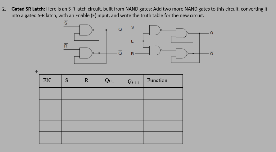
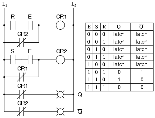
The sr flip flop is said to be in an invalid condition meta stable if both the set and reset inputs are activated simultaneously. Explain why the inputs to the latch circuit are not active low as they were before the addition of the two extra nand gates. The truth table for the d latch is. Let s explore the ladder logic equivalent of a d latch modified from the basic ladder diagram of an s r latch.
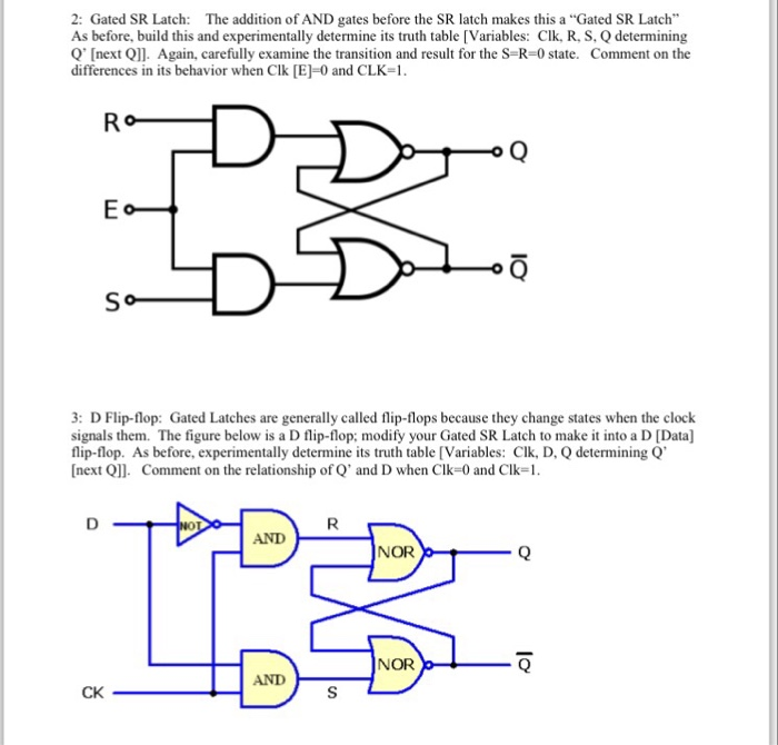
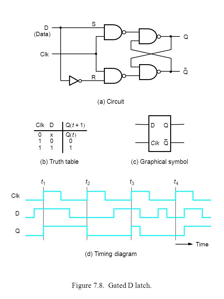
The d latch is nothing more than a gated s r latch with an inverter added to make r the complement inverse of s. The design of d latch with enable signal is given below. Sr flip flop is the simplest type of flip flops. Sr flip flop can also be designed by cross coupling of two nor gates.
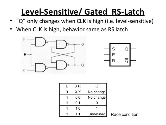
Sr flip flop construction logic circuit diagram logic symbol truth table characteristic equation excitation table are discussed. The table below summarizes above explained working of sr flip flop designed with the help of a nand gates or forbidden state. When s 0 and r 1 then by using the property of nand gate if one of the inputs to the gate is 0 then the output is 1 therefore q becomes 1 as s 0 putting the latch in the set state and now since q 1 and r 1 then q becomes 0 hence q and q are complement to each other. This latch exploits the fact that in the two active input combinations 01 and 10 of a gated sr latch r is the complement of s.
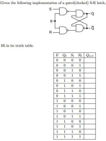
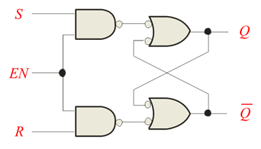
You can learn more about d flip flops and other logic gates by checking out our full list of logic gates questions. Unclocked s r flip flop using nor gate. The input nand stage converts the two d input states 0 and 1 to these two input combinations for the next sr latch by inverting the data input signal. Add two more nand gates to this circuit converting it into a gated s r latch with an enable e input and write the truth table for the new circuit.
Now when the s input goes back to 1 the circuit. A gated sr latch is a sr latch with enable input which works when enable is 1 and retain the previous state when enable is 0. Then a simple nand gate sr flip flop or nand gate sr latch can be set by applying a logic 0 low condition to its set input and reset again by then applying a logic 0 to its reset input. The logic diagram the logic symbol and the truth table of a gated d latch are shown in the figures below.
Reveal answer follow up question. 2 sr latch using nand gate. The circuit of sr flip flop using nor gates is shown in.
